Preface
We all know that PV module is an important part of PV power system and the cost of the module accounts for half of the cost of PV system. However, how much do you know about the work of PV modules, their composition, production, calculation of efficiency and related parameters? Today let me introduce the basics of PV modules in detail.
1. Solar power generation principle
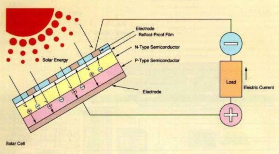
The P-N junction is the most basic structure that constitutes a solar cell. Its main function is to separate the electron-hole pairs generated by light and produce an electric potential difference at the two ends of the junction under the action of its built-in electric field. When connected to a load, a directional movement of current is generated, and electrical energy is delivered with the current.
Simply put, the principle of solar power generation is to convert solar energy into electricity. It is connected to the grid or battery through an external circuit to form a grid-connected photovoltaic system or a stand-alone photovoltaic system, respectively.
2. Components of the module and the technical performance of each part
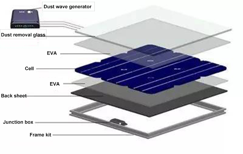
PV modules are mainly composed of tempered glass — EVA — cell string — EVA — backsheet — aluminum frame — junction box — connectors.
1) Tempered glass: protects the cell, is waterproof, anti-UV, has high light transmission, has strong impact resistance, and long service life. The general thickness is 3.2mm, and the light transmission rate is more than 90% in the wavelength range (320-1100nm) of crystalline silicon solar cell response. It has high reflectivity for infrared rays with wavelengths greater than 1200nm and can also resist solar UV radiation.
2) EVA: It plays a bonding role between cell and glass, cell and TPT. After curing, the light transmission rate is more than 90%.
3) Battery string: power generation.
4) Backsheet: Insulation, moisture-proof, anti-UV, impermeable, aging resistant, corrosion resistant.
5) Aluminum frame: protects the module, connects the installation, and has strong impact resistance.
6) Junction box: lead to the sink bar, while by configuring the bypass diode, reduce the shadow shading and hot spot brought about by the impact.
7) Plug: connection role.
3. Module fabrication process and production process
Module production process:
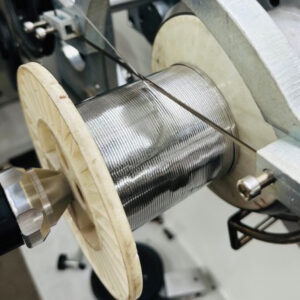
The first step is single-piece welding: Weld the battery pieces to the PV tabbing wire (tin-coated copper strip) to prepare for the series connection of the battery pieces.
The second step is welding in series: connect the cells in series according to a certain number.
The third step of laying: continue to connect the battery strings to the circuit, and at the same time protect the battery slices with glass, EVA film, and TPT backplane. (EL test)
The fourth step of lamination: bonding and fusing the battery sheet and glass, EVA film, and TPT backplane under certain temperature, pressure and vacuum conditions. (EL test)
The fifth step cleaning: to ensure the appearance of the components.
Step 6: Frame: Protect the glass with an aluminum frame and facilitate installation at the same time.
The seventh step of electrical performance test: test the insulation performance and power generation of the components.
Finally packed into storage.
4. Calculation of the power of module and cell
Module efficiency = power of the module/area of the module (length of the module * width of the module)*(1000W/m2)*100%
Cell efficiency = power of the module / (area of each cell * number of cells) * (1000W/m2) / (1 – power loss) * 100%
The power loss is generated by the cell packaging module process. It mainly consists of two parts, one is the structural change, mainly the glass and EVA materials reduce the light input and absorption; the other part is the electrical connection loss, mainly the loss caused by the connection materials such as welding tape.
Generally speaking, the encapsulation loss of polycrystalline uncoated glass is about 3-3.5%, coated glass is about 1.5%-2%, and monocrystalline is about 3-3.5%.
5. The meaning and process difference between less and more grids
The filling is greater than that of a cell with fewer grid lines. But from the power does not seem to see the advantage. The current is slightly higher for less grids and the filling is lower, while the current is slightly lower for more grids and the filling is higher. In order to improve the filling factor and reduce the series resistance of the module, module manufacturers have developed multi-gate cells. There is also the consideration of customer needs. Because the multi-gate has more main grids, so the shading area is larger, and the series connection is smaller with more main grids. So the filling is raised, so with the same wafer and process, doing multi-gate is a little less current and a little higher filling than doing less gate.
The cell technician said that for ordinary cells, both multi-gate and less-gate are similar. For high-efficiency cells, because the current of high-efficiency cells is higher, it is important to reduce the series connection. According to the printing standard marked on the workshop, the light area of multi-gate is smaller than that of less-gate. The sink of multi-gate is better, which simply means that the current runs a shorter distance. Because the resistance inside the semiconductor is greater than inside the conductor, the resistance of a multi-gate cell will be smaller.
6. The main parameters affecting solar modules
a) Parameters under STC standard test conditions: The main nominal data available are based on the STC conditions, i.e:
1. ground 2. light intensity 1000W/m2 3. atmospheric quality AM1.5 4. temperature 25℃ (cell temperature)
b) NOCT module normal operating parameters: i.e., the parameters under the conditions of 800W/m2, AM1.5, wind speed 1m/s, and ambient temperature 20℃ are mainly used as an important reference value for customers, because in practice, the parameters under this condition are closer to the actual situation.
c) Voc open circuit voltage: The voltage value of the module without load, the maximum voltage in this case.
d) Isc short-circuit current: the current of the module without load and with the positive and negative terminals connected directly, in this case the current is maximum.
e) Vmpp Maximum Peak Voltage: The voltage value at the maximum power point.
f) Impp Maximum peak current: The current value at the maximum output power.
g) Temperature coefficient:
Some properties of a material change with temperature. By temperature coefficient, we mean the rate at which the physical properties of a material change with temperature.
For components, this parameter characterizes how the current, voltage, and power of the component changes with temperature. Currently, we have only three values of temperature coefficient in our specification: open circuit voltage, short circuit current and peak power. Only the short-circuit current and temperature are positively correlated, and the voltage and power are negatively correlated. That is, the short-circuit current will become larger as the temperature rises, and the voltage and power will decrease as the temperature rises. Therefore, temperature is a factor that must be considered when designing the maximum number of series connections for a component.
-
 0.9*0.22 mm PV Tabbing Ribbon for Solar PV Modules
 - 0.6*0.18 mm PV Tabbing Ribbon for Solar Panel
- 1.1*0.18 mm PV Tabbing Ribbon for Solar Modules
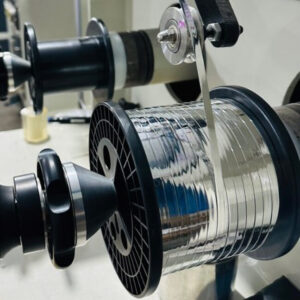
- 5*0.35 mm PV Busbar for Solar PV Modules
- 3*0.35 mm PV Busbar for Solar Modules
- 3.5*0.35 mm PV Busbar for Solar Panel
- 1*0.18 mm PV Tabbing Ribbon for Photovoltaic Modules
- 4*0.35 mm PV Busbar for Photovoltaic Modules